Sunday, June 5, 2016

Head Mechanicals

Controlled from within the ball

The head movement pieces will be done from within the main ball area, unlike some builds where there are motors in the dome itself.

Here is a rendering from James Brutan's cad drawings showing the assembly of parts to allow the dome to move around via a magnetized assembly system.


Note, the Green items are made from flexible filament and allow the red items (N52 magnets) to move about as the system pulls it around.  We will review each of these over the next few days, print them and assemble.

You can purchase the N52 magnets on Ebay (only place I could find where these are due to size and scale.  Also you will need 3 NORTH and 3 SOUTH magnets.


Here is a great list of key items for building the GIMBLE and control assembly system

Qty
Part Type and Name
Cost
Where
3
N52 Neodymium Cylinder Magnet 25mm dia x 20mm 6.5mm Hole Counterbore (SOUTH)
30
Used to attach to the head gimble
3
N52 Neodymium Cylinder Magnet 25mm dia x 20mm 6.5mm Hole Counterbore (NORTH)
30
Used to attach to the top of the gimble
1
8mm screw
7.00
Main Axle
2
Flex Printing Drive Wheels


90.00
Total: 200.00
Used for the drive wheels Flex print
4
These bearings are used to hold the 8mm studs in place.


12.22

2
HS 805bb Plus servos
102.00
Used for the Pull/push of the gimble arm
8
4mm screws for assembly of parts


1
HS 564 Hi torque servo

35
Turn the magnets 360'

Lets cover the design

The GIMBLE assembly

The Gimble as he refers to it, is a large assembly that contains:
  • A servo that spins the magnet controls.
  • 2 servos push/pull against it to form a triangle method (delta) movement function moving the dome above on the outside of the ball using very strong magnets (N52).
The main unit will have a cross connection to the main banana's cross bar.


Magnet Assembly (Head)

The NORTH magnets are located round base unit that allows positioning based on slotted openings.  The same green flexible holders are present as well as the magnets this time pointing down to the curvature of the body's ball shape.

Below is a 3D rendering of the magnet assemblies inside and outside of the ball as well as positioning of the wheels for the dome.

Magnet assembly (body)

This is the carrier that holds the SOUTH N52 magnets surrounded by flexible padding that holds the magnets into their sockets allowing some flexible movement as the unit moves against the outer part of the ball inside.
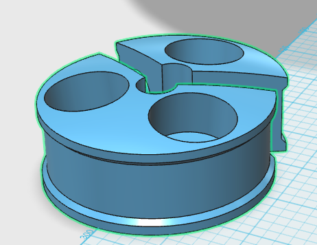


The assembly contains flexible items that provide flex to the magnets, and M8 rod that runs through and into the magnet assembly piece above.


Green Items: Flexible
Red Items: Magnets N52
Blue: Assembly for holding the magnets and connecting to the M8 rod system.




Saturday, May 28, 2016

Custom Flex-struder for wheels and assembly

Printing Flexible Material
Has been the holy grail for many printer owners... most printers come with their own custom MK7 or 8 branded partial extruder assemblies.  These kits generally have the heat throat that goes from under the extruder frame into the heating block and nozzle.

These extruders are common in most printers... below is a typical MK8 extruder...
I have these connected to universal mounts that allow me to add/remove them from the 2 large CNC printers I have.

Neither print flexible materials... they get jammed or never extrude correctly.  Plus neither printer has a heated bed.

Until...

I developed the perfect extruder that I will be packaging and possibly selling on Amazon shortly.

The good news:
  • Its a modified MK8 extruder - thus it fits into 90% of the printers out there.
  • It can be easily assembled - it has 2 modifications outside the typical MK8
  • It is low cost - it is made using existing MK8 parts.

Here are the items I generated:

Extruder Base has a deep enough ridge to catch the flex material and keep it snug while it makes its way into the throat assembly.  No clogging.


The extruder tension arm is based off the typical HicTOP model extruder arm


When combined with the typical bearing for pressing against the motor gear, these make a very tight and compressed path that works perfect for the flexible filaments.

Lastly we need the special bottom block used with the HicTop or other extruders that use partial plastic pieces.


With the assembly together using the existing cooling fins, fan and metal protective cage.  The unit simply sits back in the printer as the old MK8 did.

Printing flexible items as we speak...


Sunday, May 8, 2016

Lens for Radar Eye Installation

After the print finished, the radar pieces looked great.  The actual images I have seen show the internal parts a little more extruded from the frame or back plate but this will suffice.

I am going to stick with the 70mm sphere since I need to simply shave down the outer edges to "shrink" the diameter of the sphere.

Taking a belt sander, I simply ran the sphere on it several times each time breaking off the molten/hardened plastic formed from it... slowly it shrunk the diameter of the sphere.  I then checked it against the template band that was printed out and it was real close.

Time for the fitting

Placed the lens into the pocket and pushed it into the other side, slightly bending it to get inside the plastic.

Presto!

Works!


Saturday, May 7, 2016

Dome Assembly Part 2

Printing Redux


We had a few issues with finding the correct diameter as well as look for the dome's Radar Eye pieces.

  • My first order was for 70mm sphere (christmas ornament) this was too small
  • My Second order was for 80mm sphere (another christmas ornament) this seem too big as well as I didnt realize it had gold glitter on it...!


So...

I am trying to find a sphere that will fit within the radar eye pieces and look correct.

Radar eye re-print

I had to reprint the radar eye pieces, previously I had printed the internal parts and the outer lens but not the backing... so this time I combined the internal pieces and backings to form 1 single unit.

I combined the 2 and made 1 piece to print.


This will take 4 hours to print... at High resolution .1mm layers.


Saturday, April 30, 2016

Dome Assembly Part 1

Putting the pieces together (PLA Welding)


After my trip to NYC to see daughter... got back into actually assembling all the pieces for the main dome structure.

Items needed for assembly:
3 1/3 pieces of the dome printed 3D
3 1/3 pieces of the under carriage or skirt printed 3D
3 1/3 pieces of the lower band between the skirt and the upper dome pieces.
#16 weld-on in tube with glue tip


The PLA Welding will require

A rotary tool (Don't bother trying to use cordless - battery goes dead in 5mins) such as a dremel or cheap rotary drill from harbor freight.
1/8" chuck mount to apply the filament to (used for PLA welding).
Extra white filament to use for welding.


Dremel with adjustable chuck.


You will cut 1-2" strips of filament (1.75mm) and straighten it to insert into the chuck of the drill.  This will rotate at high speed to basically melt and weld the plastic pieces together.  This also forms a bond that is stronger than glue and helps create a lip large enough to file down and sand.


Need solder cutter/pliers which are awesome for this purpose of trimming.


Dry fitting the pieces

First we dry fitted the pieces together to see where the prints didn't align correctly and where I would have to adjust pieces with a hobby knife.

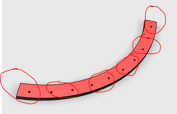
The lower band (this piece will be made to look like silver/metal) has the pilot holes to align and connect the dome upper pieces together.  I used this to help guide the 3 pieces together above as well as overlap each piece to create a strong bond during gluing.

Applied some #16 to the bottom and placed each dome piece onto the lower bands... once completed I used screws #4-40 3/8" screws to keep them aligned while it dried.

I then went to work welding the dome slices together
You can see welding plastic examples watching these YouTube videos:


Once completed with the first try of all the seams... I then took a metal file and began filing down the seams till they were flat as the rest of the sides...  For the first try it is already looking great.  Will need to apply some more plastic to some areas where there are cracks etc... but welding definitely works!


The dome shell is assembled... needs some more welding and gap filing.


Some of the texture lines will need to be filed out but that seam which is in the middle is only noticeable due to the darker it appears in the photo.


This seam here is needing to be filed... you can see where the plastic is raised before I file it down.


Sunday, April 10, 2016

Hardware Breakdown for the Cheese and Hub sections - The Banana

The Banana

Hardware needed to assemble the drive carriage, also known as "the Banana".


I am trying to help others here by posting what I have sourced so far for parts to complete and assemble the Hub and Motor sections.

NOTE: This is following James Bruton's XROBOTs.co.uk BB8 version 3 build...

The altercation below is with the small wheels... the larger drive wheels I will not be able to get away with, but the smaller wheels I found baggage replacement wheels are the same size and configuration as what James' printed using his Lulzbots nanjaflex extruder setup... my printers do not print flexible material very well - if at all... so I will have to source out a online printer to help print the main drive and banana drive wheel surfaces...

Parts:
Qty
Part Type and Name
Cost
Where
6
8.00
Small outer wheels on banana
21
7.48
Small outer wheels on banana
2
M6 120mm bolts
7.39
Small inner wheels on banana
27
4-40 7/8" Screws
8.53
Small Wheel Screws for assembly
12
4-40 1/2" screws
7.91
Banana frame assembly support
9
6x19x6 Bearings
6.56
Small Wheel for assembly
2
30x62x16 Sealed bearings
10.43
Banana axle assembly
24
4-40 Blind Nuts
5.51
Banana frame assembly to wheel assemblies
27
4-40 hex nuts
11.95
Small Wheel Assembly
20
4-40 1" screws
7.29
Banana frame assembly to parts
3
4-40 Nut common
8.96
Small Wheel Inner connection spacer
2
Front Windshield Wiper Motors
25.00
Drive Motor assembly
20
Luggage Wheels (50mm x 18mm x M6)
50.00
Small Wheels (instead of printing)

Another great shot of the banana outside the cheese...


Sunday, April 3, 2016

The Main Drive and Outer Hub

The Main Drive and outer hub is where we will start with the assembly.  Following James Bruton's Awesome video series and informational blog... we will start work on the hub and main drive systems.

The hub

Known as the "cheese" from Mr. Bruton consists of 20 barrel like slices connected to outer rings that keep its shape.  It is 300mm wide which is 100mm wider than his version 2.


Each slice on his printer took roughly 4hrs with ABS.  I am printing each one in PLA at 40% infill and .26 layer height with 3 parameters which takes 10-11hours each.
Total time to print these is 240hours from start to finish. 

Thank God I have 2 printers...

NOTE: Most of everything that we will be printing will be using the following settings:

Layer Height: .26
infill: 40%
Parameters: 3
TopFill: 3
BottomFill: 2
Speed: 60mm/s

Nozzle: .4
Filament: 1.75


The Cheese consists of the 20 slices and 2 outer rings all connected via screws #4-40 1/2" and Weld-On 16 solvent...


Once the cheese is assembled you will need to file and fill many uneven spots on this hub because the more smooth and circumference is.. the better the rolling and hub movement with the motor.


After printing each one... used Weld-On 16 to assemble the pieces


Assembly is basically connect a inner ring to cheese piece with screws (4-40 1/2") and glue... you can never over glue these pieces... we are looking for it to be ridged and strong.

1 inner ring piece looks like this:


So we need to offset the slices so a slice is connected to 2 of these and bridges the connection between ring pieces (4 parts).


You offset each slice (here is a markup of where you will connect the slices.
On the very first piece, I suggest starting from the most inner piece and working you way 1 or both directions.


Here is some photos of my first 2 rings connected via the slices... making my way around.


Notice the last slice(s) here are connecting or bridging the next inner ring piece as an alignment...


Great view of 2 inner prints connected and bridged as well as completed before starting on the 2nd half of the cheese.


And the 3rd inner ring is connected and progress continues...  The great thing about Weld-On 16 is it dries in like 1 minute.  In 10 minutes its as hard as a rock!  But because of its gel-like properties its great for positioning pieces before it hardens.


Another view of 3rd section being connected and bridged by a slice... and adding continues.


Almost there...


Another piece and notice I have to use a slice to bridge the last ring into place.  This also indicates if you connected them right and adjustments will be made here to align the ring.


This is a great example of what type of sanding, filing and filling will have to be done to get this smooth... see how this slice is offset from the 2 adjacent to it.

The final piece assembled and dried... looks great!